Ray Tracer
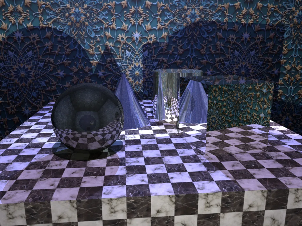
A recursive ray tracer with Phong illumination, texture mapping, shadows, reflections, refractions, and ray-differential-based anti-aliasing.
Overview
Ray tracing renders an image by simulating light in reverse. For each pixel, a ray is shot from the camera into the scene, the closest intersection is found, and the surface color is computed from the lights it can see. Mirrors and glass recurse: reflection rays bounce off surfaces and refraction rays bend through them, and the results blend into the final color.
Primary rays
One ray per sub-pixel sample, from the camera through the image plane; intersect against spheres, cones, cubes, and meshes.
Phong illumination
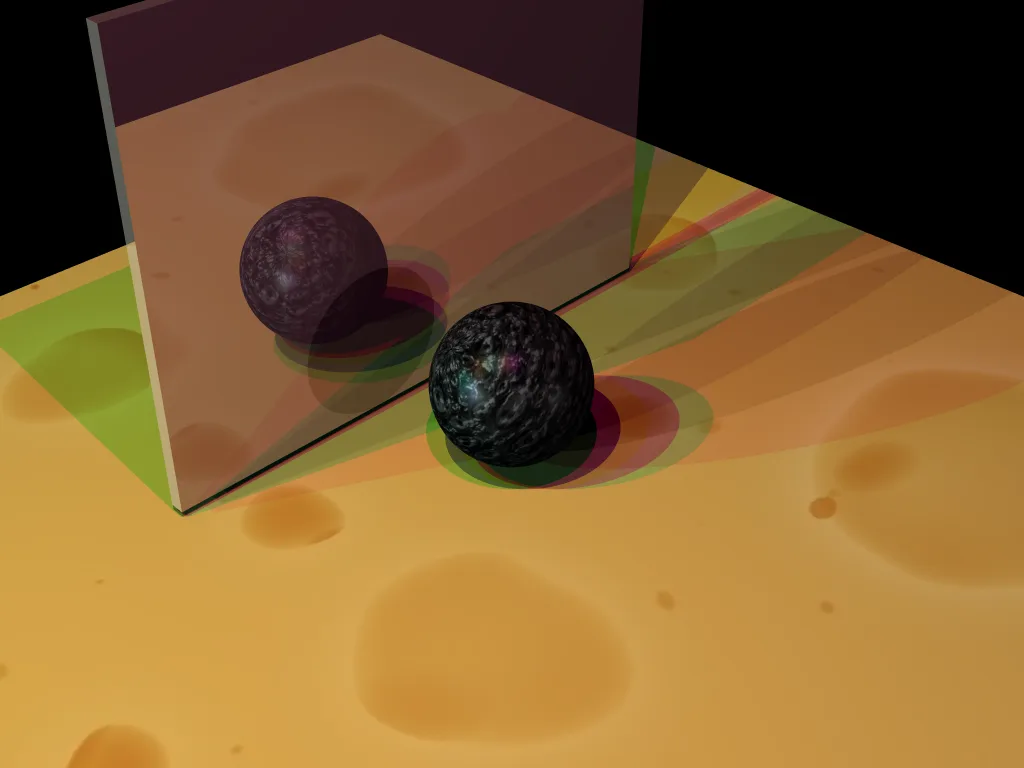
Ambient, diffuse, and specular terms accumulated over point, directional, and spot lights.
Shadow rays
Before adding each light's contribution, a ray is cast toward the light. If geometry blocks it, the light is skipped.
Reflection & refraction
Mirror rays reflect about the normal; refraction follows Snell's law, falling back to total internal reflection when no exit angle exists.
Ambient \((k_a)\) approximates indirect light; diffuse \((k_d)\) scales with how directly the light hits the surface; specular \((k_s)\) creates highlights where the reflected light direction \(R\) aligns with the view direction \(V\), sharpened by the shininess exponent \(s\).
Texture aliasing & ray differentials
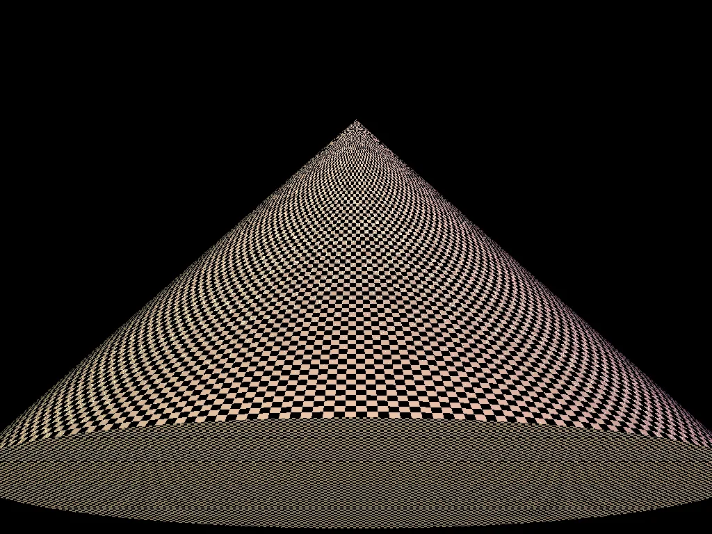
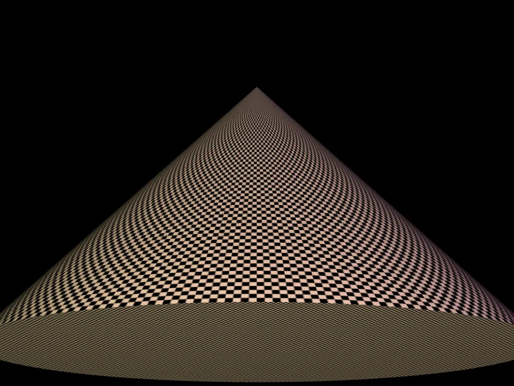
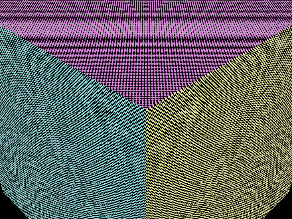
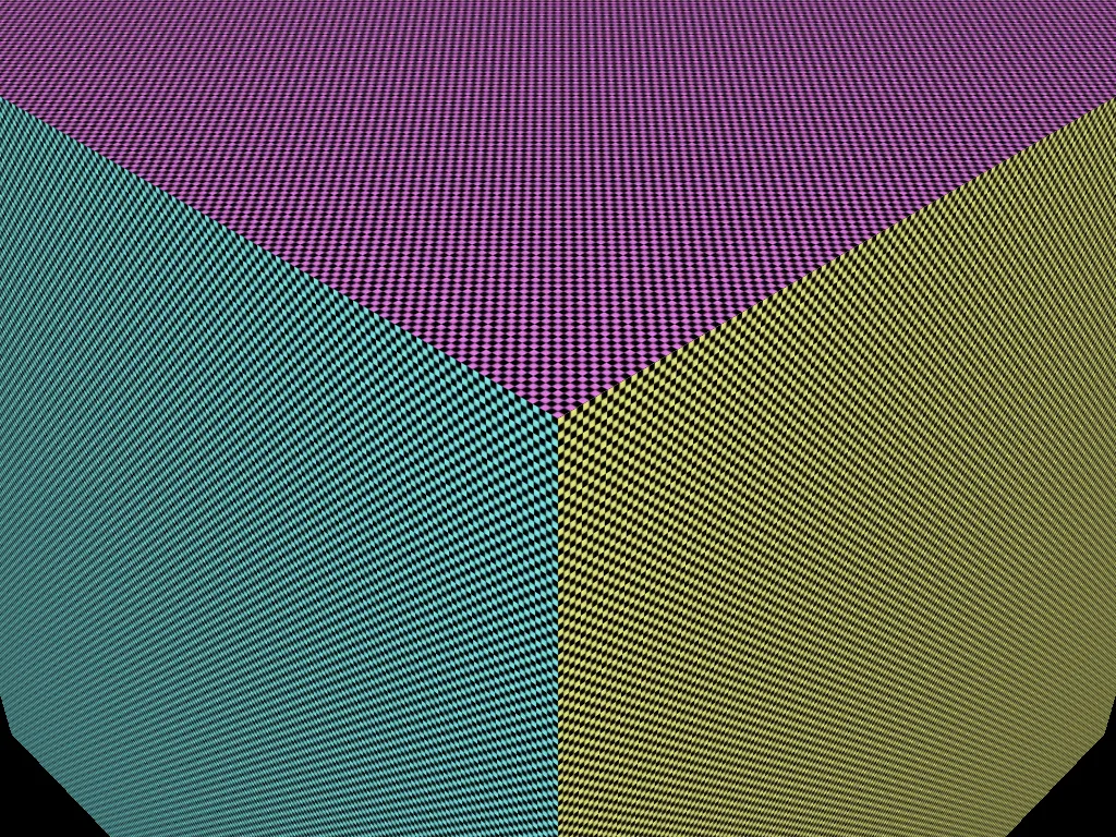
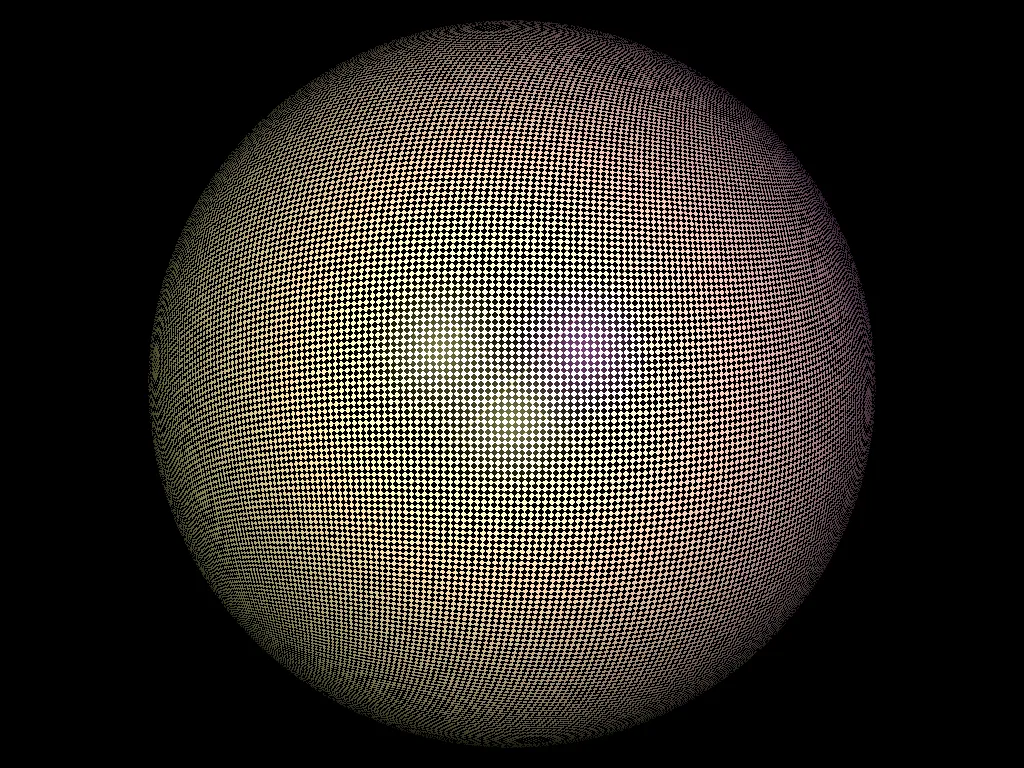
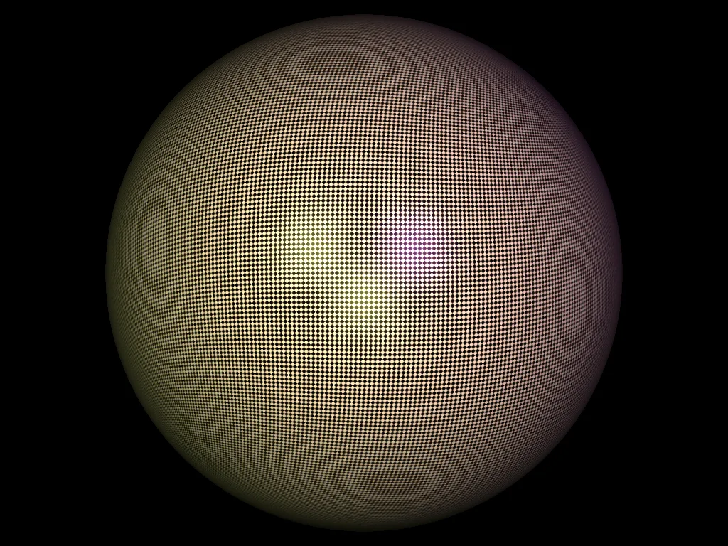
The sliders below show a classic failure mode: a checkerboard receding into the distance shimmers into noise. The cause: a single distant pixel covers a huge area of texture, but a naive lookup samples just one point of it, so neighboring pixels land on unrelated texels.
The fix has two parts:
Pre-filtered pyramid
The texture is repeatedly downsampled into a pyramid, so a correctly averaged version already exists for any footprint size.
Track the pixel footprint
Alongside each ray, track how its hit point moves when the ray is offset by one pixel. This gives the exact texture-space footprint each pixel covers, which selects the mip level.
Sampling the two nearest mip levels bilinearly and blending between them (trilinear interpolation) produces the smooth, stable result on the right of each slider.
Ray differentials & the chain of spaces
A ray differential is the answer to a simple question: if this ray had come from one pixel over, where would everything land instead? Formally, each ray carries four extra vectors: the derivatives of its origin and direction with respect to the pixel coordinates, \(\partial\mathbf{o}/\partial x\), \(\partial\mathbf{d}/\partial x\), \(\partial\mathbf{o}/\partial y\), \(\partial\mathbf{d}/\partial y\). To compute them, differentiate every transform a ray passes through on its way from a pixel index to a point on a surface.
Integer grid
A pixel index \((i, j)\) with the origin at the top-left, where rows grow downward, so y will need a flip.
Normalized device coords
Resolution-independent coordinates in \([-1, 1]^2\), centered on the image, y pointing up.
Point on the film plane
NDC scaled by the field of view and aspect ratio onto a virtual film plane one unit in front of the eye.
The actual ray
The camera-to-world matrix carries the film point into the scene; normalizing gives the ray direction.
Dividing by the resolution and remapping \([0,1] \to [-1,1]\) removes the image size from all later math; the subtraction order on \(y_n\) flips the downward pixel rows into an upward axis.
\(\tan(\theta_h/2)\) is the half-height of the film plane one unit away. A wider field of view stretches the plane and the aspect ratio \(a\) widens x to keep pixels square. In camera space the eye sits at the origin looking down \(-z\), so the film point doubles as the ray direction.
\(M_{cam\to world}\) is the inverse of the view matrix. The film point transforms with \(w = 0\): it's used as a direction, so it should rotate but not translate.
Everything up to normalization is linear, so its derivative is just "one pixel's worth of film plane" pushed through the same matrix. Normalization is the only nonlinear step: the projector \((I - \mathbf{d}\mathbf{d}^T)\) keeps the component of the change perpendicular to \(\mathbf{d}\). Sliding a unit vector can only rotate it, not lengthen it. For a pinhole camera \(\partial\mathbf{o}/\partial x = 0\): all rays leave the same point.
Differentiating \(P = \mathbf{o} + t\mathbf{d}\) needs \(\partial t/\partial x\), how much sooner or later the neighboring ray hits the surface. Constraining the offset hit point to stay on the tangent plane gives the first equation; note the \(\mathbf{d}\cdot\mathbf{n}\) in the denominator, which is why footprints stretch at grazing angles, exactly where texture aliasing is worst.
The last hop leaves world space entirely. The surface's own parameterization provides tangent vectors \(\partial P/\partial u\) and \(\partial P/\partial v\) (for a sphere or cone, differentiate its UV formula; for a mesh, they come from the triangle's vertex UVs). Expressing \(\partial P/\partial x\) in that basis is a tiny 2×2 linear solve, and its solution \(\partial\mathbf{uv}/\partial x\) is precisely the texture-space footprint that the mip level formula above consumes. One derivative, carried through five spaces: pixel, NDC, camera, world, and finally UV.